Hotline:86 18705139836
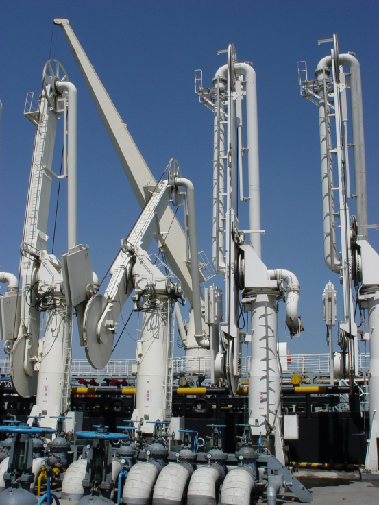
Marine loading arm is a special equipment for transferring liquids or gases between docks and tank ships with rotary joints with various characteristics such as flexible rotation, good sealing and ability to adapt to harsh environments
l During transmission, it follows the tank ship within the normal drift range of the tanker;
l Depending on the loader arm size, model and load, manual operation or electro-hydraulic control is possible;
l Depending on the type of medium and temperature being transported, the loading arm can be designed to be made of carbon steel, stainless steel or aged PTFE carbon steel pipe;
l DN:DN100~DN400
l The design temperature range is :196°C~+300°C
l The design pressure is:PN-0.095Mpa~PN6.0Mpa;
l Equipped with an emergency disengagement system, which can realize the emergency disengagement of the tank ship from the loading arm.
~
Structural form code:
1-Self-supporting double counterweight marine loading arm
2-Hybrid support single counterweight marine loading arm
3-Independent support single counterweight marine loading arm
4-Independent support single counterweight marine loading arm (double pipe)
Drive mode:
M-Manual type
H-Hydraulically actuated type
Marine loading arm Design conditions
Terminal tonnage size, water level drop, tank ship size, loading and unloading medium, medium pressure, medium temperature, wind load and seismic load are necessary conditions for the design of marine loading and unloading arms |
For environmental data, if there is no special requirement from the customer, the design is according to the following standards |
wind speed:Reset status:55m/s working status:20m/s |
Wind load:55m/s-20MPa 20m/s-2.5MPa |
Earthquake coefficient:0.2G |
Typical allowable flow
Loading arm caliber | allow traffic m3/h |
DN150 | 500 |
DN200 | 1100 |
DN250 | 1750 |
DN300 | 2500 |
DN350 | 3000 |
DN400 | 4000 |
The distance between the center of the boat arm and the edge of the pier
Berth tonnage | Arm caliber
| Arm spacing(m) | The distance from the center of the column from the edge of the pier(m) |
Below 10,000 tons | DN150 | 2.0 | 1.5-2.0 |
10,000 tons | DN200 | 2.0-2.5 | 1.5-2.0 |
20,000 tons | DN200-DN250 | 2.0-2.5 | 1.5-2.0 |
30,000 tons | DN250 | 2.0-3.0 | 2.0-2.5 |
50,000 tons | DN300 | 3.0-3.5 | 2.0-2.5 |
80,000 tons | DN300-DN400 | 3.0-3.5 | 2.0-2.5 |
100,000 tons | DN300-DN400 | 3.5 | 2.5-3.0 |
200,000 tons | DN400 | 3.5 | 2.5-3.0 |
Typical load data
Arm caliber
| Shape | Vertical load (KN) | Horizontal load(KN) | Overturning moment (KNM) |
DN150 | AM61 | 40 | 19 | 108 |
DN200 | AM61 | 56 | 22 | 125 |
DN150 | AM63 | 62 | 38 | 230 |
DN200 | AM63 | 87 | 45 | 286 |
DN250 | AM63 | 110 | 53 | 350 |
DN300 | AM63 | 190 | 90 | 850 |
DN150/DN100 | AM64 | 75 | 45 | 260 |
DN200/DN100 | AM64 | 90 | 50 | 300 |
The number and caliber of marine booms are selected
Berth tonnage | Number of boat arm loading slipways (Number of ship arm unloading slipways) | ||||
DWT | DN150 | DN200 | DN250 | DN300 | DN400 |
1000 | 1(1) | ||||
3000 | 2(1) | ||||
5000 | 2(1) | 1(1) | |||
10000 | 2(1) | 1(1) | |||
20000 | 3(2) | 2(1) | |||
30000 | 3(1) | 2(1) | |||
50000 | 3(2) | ||||
80000 | 3(2) | 2(1) | |||
100000 | 3(2) | ||||
200000 | 3(2) | ||||
Marine arm floor size
The standard base plate size of the marine arm is shown in the table below, which can be made according to customer requirements.
The height of the embedded bolt extension positioning plate is: bottom plate thickness + 2 nut thickness + 50mm
Arm caliber | Baseboard size(A) | Large aperture spacing (B) | Small hole spacing (C) | Baseboard thickness δ | Number of holes N-φ | Embedded bolt specifications
|
DN150 | 1000 | 1140 | 140 | 30 | 8-Φ36 | M32 |
DN200 | 1200 | 1260 | 170 | 30 | 8-Φ36 | M32 |
DN250 | 1400 | 1360 | 170 | 30 | 8-Φ42 | M36 |
DN300 | 1500 | 1640 | 170 | 40 | 8-Φ42 | M36 |
DN350 | 1600 | 1860 | 210 | 50 | 8-Φ42 | M36 |
DN400 | 1800 | 2100 | 210 | 50 | 8-Φ46 | M42 |

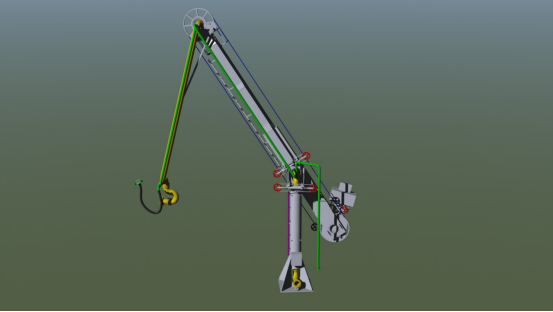
AM61 Marine loading arm
Main components:
l High point swivel joint
l Outer arm
l Inner arm
l Ship-end connection flange
l Counterweight beams
l Locking device
l SYD-JZJ
l Inlet flange
l Emptying port
l Outer arm weight
l Counterweight beam
l Vacuum short-circuit system
l 3D connectors
l Columns
Technical parameters:
DN:DN100、DN150、DN200
Pipe material: carbon steel, stainless steel
Optional accessories:
l Vacuum short circuit
l Emptying system
l Insulating flange
l Manual QCDC
Character:
Self-supporting structure, internal and external arms have independent counterweight systems, pipeline system adopts variable section structure, all external loads and bending moments are borne by rotary joints.
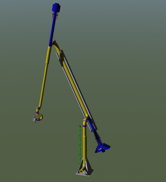
AM63 Marine loading arm
Manual
Hydraulic
Main components:
l Upper rope wheel l
l Lower rope wheel l
l Outer arm drive l
l QCDC l
l Rotary drive l
l Outer arm l
l Outer arm support l
l Inner arm l
l Counterweight l
l Base l
l 3D joint l
l Inner arm drive l
l Inner arm support l
l ERC
Technical parameters:
DN:DN100、DN150、DN200、DN250、DN300、DN350、DN400
Pipe material: carbon steel, stainless steel
Optional accessories:
l Vacuum short circuit l
l Emptying system l
l Insulating flange l
l Manual QCDC, hydraulic QCDC l
l ERC
Features: Only the pressure inside the line and the stress generated by the weight of the medium act on the rotary joint and the pipeline. The support system adopts a large diameter slewing ring to effectively reduce frictional resistance and is light to operate. The diameter of the swivel joint and the pipe is uniform. The line is suspended on the support system, effectively eliminating additional stresses caused by temperature changes.
The counterweight system keeps the loading arm in balance at any position, and balances the inner and outer arm movements through the follow-up counterweight device.
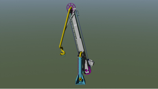
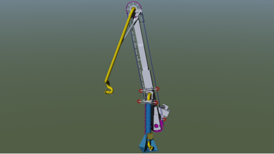
AM64 Marine loading arm
Main components:
l Upper rope wheel l
l Lower rope wheel l
l Outer arm drive l
l QCDC l
l Rotary drive l
l Outer arm l
l Outer arm support l
l Return air line l
l Inner arm l
l Counterweight l
l Base l
l 3D joint l
l Inner arm drive l
l Inner arm support l
l ERC
Technical parameters::
DN:DN100、DN150、DN200、DN250、DN300、DN350、DN400
Pipe material: carbon steel, stainless steel
Optional accessories:
l Vacuum short circuit l
l Emptying system l
l Insulating flange l
l Manual QCDC, hydraulic QCDC l
l ERC
Features: Only the pressure inside the line and the stress generated by the weight of the medium act on the rotary joint and the pipeline. The support system adopts a large diameter slewing ring to effectively reduce frictional resistance and is light to operate. The diameter of the swivel joint and the pipe is uniform. The line is suspended on the support system, effectively eliminating additional stresses caused by temperature changes. The counterweight system keeps the loading arm in balance at any position, and balances the inner and outer arm movements through the follow-up counterweight device.
Marine loading arm
Work envelope diagram

Marine loading arm user provides a table of parameters
Terminal parameters
Number | Parameter name | Data |
1 | Maximum distance from the edge of the pier to the outer edge of the bumping pad A | m |
2 | Minimum distance from the edge of the pier to the outer edge of the touching pad B | m |
3 | The distance from the edge of the pier to the center of the column C | m |
4 | The difference between the quay level and the highest water level D | m |
5 | Difference between wharf plane and minimum water level E | m |
6 | Quay plane to flange center height F | m |
7 | The column center distance H | m |
8 | Maximum free space (length) I | m |
9 | Maximum free space (width) J | m |
10 | Maximum interference height above quay level K | m |
11 | Maximum load of the terminal | N/m2 |
12 | Supply voltage | V |
13 | Power frequency | Hz |
(1) Operational data
Drive mode | Hydraulic/manual | |
Control system | Central control | |
On-site control | ||
(2) Optional facilities
¨ladder escape | ¨Insulating flange | ¨Sound and light alarm system | ¨Emergency disengagement device |
¨Manual quick couplings | ¨Vacuum short circuit | ¨Column discharge device | ¨Adjustable pillars
|
¨Wireless remote control |
Contacts:
Mobile:86 18705139836
Tel:86 18705139836
Address:Add: Taolin Industrial zone, Donghai ,Lianyungang,Jiangsu,China

Copyright © 2022-2025 Junhetongda Petrochemical Equipment (Lianyungang) Co., Ltd. All Rights Reserved.
WeChat